
Put structure between the cable and the spark.
A U-channel barrel for duties where spatter, impact and maintenance access dominate. The barrel is the outer working surface; the cable bundle stays inside.
A U-channel barrel for duties where spatter, impact and maintenance access dominate. The barrel is the outer working surface; the cable bundle stays inside.
The series number is a routing decision, not a product grade. Start with the motion and environment, then let the model, bundle and service access narrow the geometry.
Start here when — and stop when.
Good starting point
- Spatter, sparks or metal particles repeatedly strike the outside of the bundle.
- The line needs a replaceable outer layer that can be inspected without opening the whole route.
- Spot welding, arc welding, forging or die-casting makes impact protection part of the brief.
- The robot has enough payload and space for a barrel structure, confirmed in the envelope.
Not the first answer
- A light, clean application does not need the extra structure or moving mass.
- The barrel has not been checked for collision, centre of gravity or service access.
- The specification assumes that every spot-welding project must use Series 4.
- A project needs a custom combination; the barrel alone is being treated as the complete answer.
Specification boundary.
| Conduit diameter (ID / OD) | φ48 (φ54.5) / φ70 (φ80) mm |
|---|---|
| Connector protection | IP54 |
| Outer construction | U-channel barrel with spring and internal conduit |
| Core material | ABS outer structure + spring |
| Typical processes | Steel and aluminium spot welding, arc welding, forging and die casting |
| Installation basis | Robot flange, J3/J4 anchors, tool interface and full envelope |
| Project release | Barrel envelope, collision check, service access, BOM and wear-part list |
Five checks before a drawing is released.
Confirm the rotation
Identify the axis, direction, maximum angle and repeated frequency. Continuous multi-turn is a separate review.
Measure the bundle
Count cables and hoses, measure the assembled outer diameter and record the minimum bend radius.
Anchor the route
Check the flange, J3/J4 fixing points and the space available around the wrist and tool.
Check the envelope
Run the barrel/bracket through the full motion envelope and check collision and service access.
Release the drawing
Agree the interface drawing, BOM, wear parts and a trial-install check before batch release.
Public references with this system.
These are model families in the public reference map. Open a brand to see the available configurations; an engineer still has to confirm the exact variant.
Selected project context.
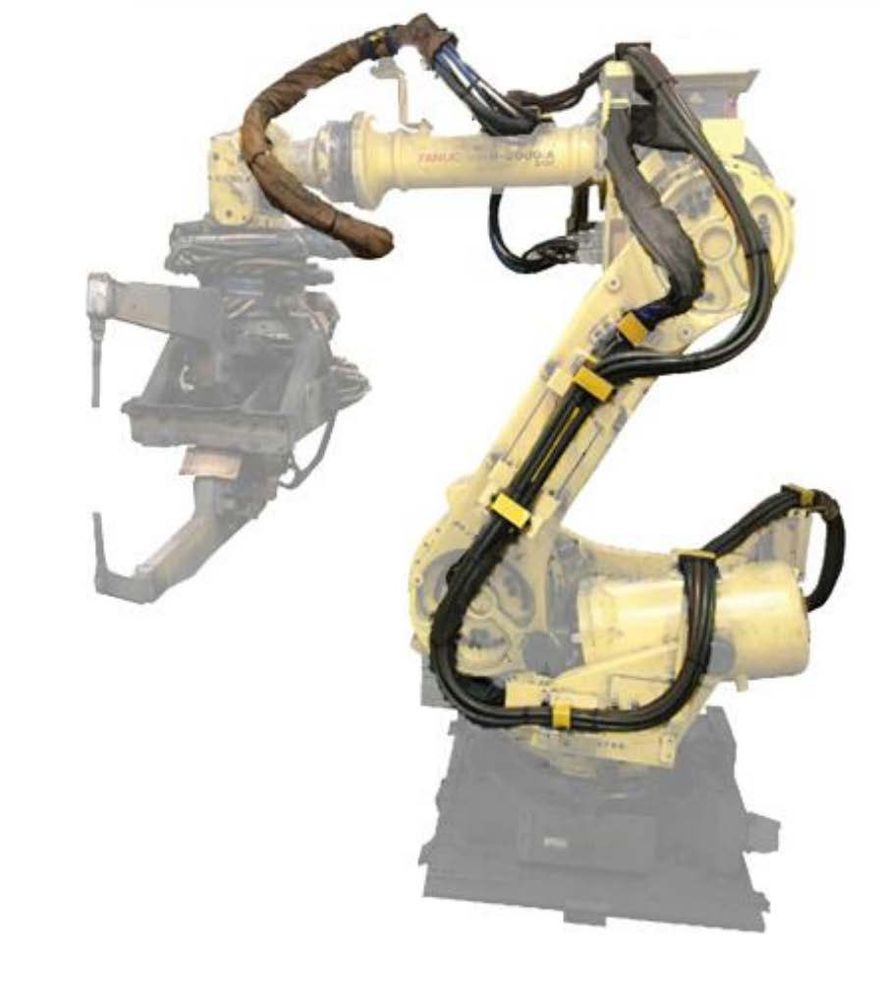 Spot + handling
A KUKA line with two duties on one interface logic
A 2025 public record combining Series 4 and Series 3 across 49 KUKA robots.
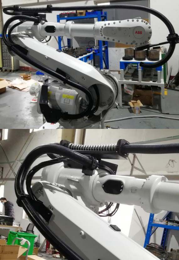 Spot / quick change
Spatter protection around a quick tool change
A 2026 public record for a FANUC R-2000iC/210F spot-welding duty.
Ask before you commit.
Does 360° rotation mean unlimited turns?
No. The bracket can follow rotation through 360°, but continuous multi-turn routing depends on the cable and hose connections and may need a slip ring or a defined turn limit.
Can this system be combined with another series?
Yes. A route can use a rotary bracket at the wrist and a spring or barrel element elsewhere. The combination should be reviewed as one assembly.
Can I select the diameter from the robot payload?
No. Diameter is selected from the assembled cable and hose bundle, its fill and the minimum bend radius. Payload only tells us how much mass the robot can carry.
What do you need for a review?
The exact robot code, tool interface, cable and hose list, photos of the wrist and a motion clip if available. A drawing cannot be released from a brand name alone.
One model. One envelope. One useful answer.
If the robot code is known, we can skip the generic kit conversation and start with the interface.